Printed Circuit Boards (PCB) are the backbone of all major electronics, from your smartphone to the satellites orbiting our planet. Ensuring the integrity of electronic components in PCBs is crucial to the functionality of these devices. This article will delve into the methods and techniques used to check electronic components in PCBs, providing a comprehensive guide for both beginners and seasoned professionals.
Understanding the Basics
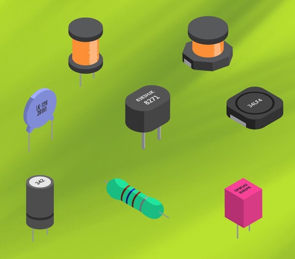
Before we dive into the specifics, it's essential to understand the basic components of a PCB. These include resistors, capacitors, inductors, diodes, transistors, and integrated circuits (ICs). Each component has a unique function and potential failure mode, requiring different testing methods.
Visual Inspection
The first step in checking electronic components in PCBs is a thorough visual inspection. This involves looking for any visible signs of damage such as burns, cracks, or discoloration. A magnifying glass or microscope may be used for this process. Additionally, check for any loose or misaligned components.
Multimeter Testing
A multimeter is a versatile tool that can measure voltage, current, and resistance. It is used to check the functionality of resistors, capacitors, and inductors. For resistors, the multimeter is set to the resistance mode, and the probes are placed on each end of the resistor. The reading should match the resistor's value. Similarly, capacitors and inductors can be tested using the capacitance and inductance modes, respectively.
Continuity Testing
Continuity testing is used to ensure that there are no breaks in the circuit. The multimeter is set to the continuity mode, and the probes are placed at the start and end of a trace. If the multimeter beeps, it indicates that the circuit is continuous.
IC and Transistor Testing
Integrated circuits and transistors are more complex and require specialized equipment for testing. An oscilloscope can be used to check the input and output signals of these components. Alternatively, a logic probe can be used to test digital ICs.
Advanced Techniques
For more advanced or complex PCBs, automated test equipment (ATE) may be used. These machines can perform a variety of tests quickly and accurately, including functional testing, in-circuit testing, and boundary scan testing.
Infrared Thermal Imaging
Infrared thermal imaging is a non-destructive testing method that can identify hot spots on a PCB. These hot spots may indicate a short circuit or an overworked component.
Conclusion
Checking electronic components in PCBs is a multi-step process that requires a keen eye and the right tools. From visual inspection to advanced automated testing, each method plays a crucial role in ensuring the functionality and reliability of our electronic devices. As technology continues to advance, so too will the methods used to test and verify the integrity of electronic components in PCBs.


