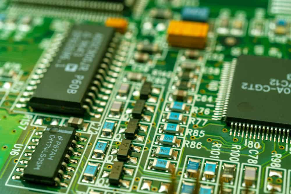
In the dynamic world of electronics, circuit boards serve as the intricate pathways that orchestrate the functionality of devices. When these boards encounter issues, the skill of identifying and rectifying faulty components becomes paramount. This exploration aims to delve into the strategies and methodologies for uncovering the bad component of a circuit board, providing a comprehensive guide for engineers, technicians, and enthusiasts.
1. Visual Inspection: The First Line of Defense
The journey to find a bad component often begins with a meticulous visual inspection. Examine the circuit board for physical abnormalities such as burnt areas, damaged components, or discolored regions. Look for signs of overheating, solder joints that appear cracked or dislodged, and any visual cues that may indicate a problematic component.
2. Use of Multimeter: Probing for Anomalies
A multimeter is a versatile tool for troubleshooting circuit boards. Utilize it to measure various electrical parameters, including resistance, voltage, and continuity. Perform the following steps:
- Resistance Measurements:
Check resistors for values within their specified tolerance. A significant deviation from the expected resistance may indicate a faulty resistor. - Voltage Measurements:
Probe different points on the circuit to verify voltage levels. Abnormal voltage readings can point to issues with specific components or power supply areas. - Continuity Testing:
Use continuity testing to identify open circuits or short circuits. It helps pinpoint areas where the electrical path is disrupted or improperly connected.
3. Thermal Imaging: Spotting Overheating Components
Thermal imaging cameras provide a non-invasive method to detect overheating components. Power up the circuit and use the thermal camera to identify areas with elevated temperatures. Hotspots can indicate components experiencing excessive stress or potential failure.
4. Signal Tracing and Analysis: Following the Pathways
Understanding the flow of signals through the circuit is crucial. Use an oscilloscope to trace signals through various components. Anomalies in signal waveforms can help identify faulty components affecting signal integrity. This approach is particularly effective for diagnosing issues in audio, RF, and digital circuits.
5. Component Swap Testing: Isolating the Culprit
In cases where identifying the faulty component remains challenging, consider component swap testing. Replace suspected components with known-good ones and observe if the issue persists. This method helps isolate the problematic component by systematically narrowing down the possibilities.
6. Advanced Tools: X-ray and Circuit Board Analyzers
For complex circuit boards with hidden or embedded components, advanced tools such as X-ray machines or circuit board analyzers can be invaluable. X-ray imaging reveals internal structures, aiding in the identification of hidden defects, while analyzers provide in-depth insights into the functioning of integrated circuits.
Conclusion: Precision in Problem Solving
In conclusion, the quest to find the bad component on a circuit board demands a combination of expertise, tools, and systematic approaches. From visual inspections and multimeter measurements to thermal imaging and advanced analysis tools, each method contributes to the precision of problem-solving. Engineers and technicians, armed with these strategies, can navigate the intricacies of troubleshooting, ensuring efficient and effective resolution of issues on circuit boards. Mastering the art of identifying and rectifying faulty components is a skill that empowers individuals to breathe life back into electronic devices and pave the way for continuous innovation in the realm of electronics.


